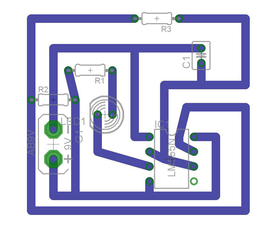
Prototyping PCBs (printed circuit boards) is an integral part of the process when designing electronic products. Once the desired circuit is created in a solderless breadboard, a circuit schematic is created in a circuit design software such as EagleCAD. Next, the board layout is created in the same program. The board layout can then be sent to a PCB manufacturer, generally overseas, to create the physical boards.
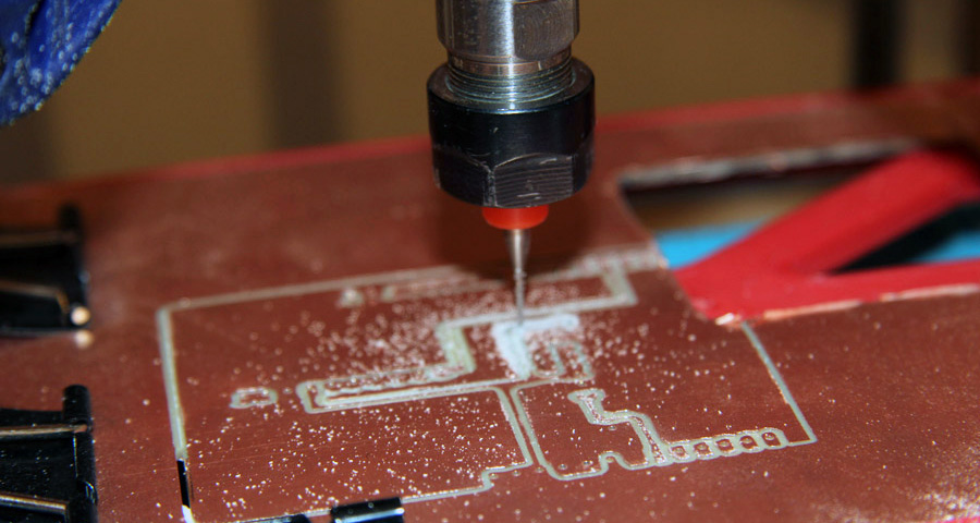
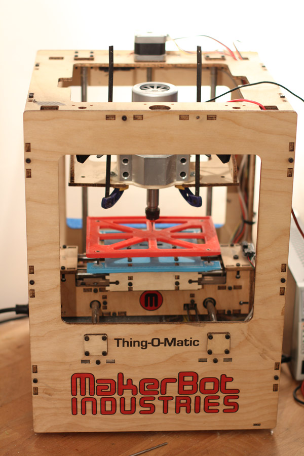
In an effort to continue testing Small Machines at Tomorrow Lab, we repurposed a Makerbot Thing-O-Matic into a circuit engraver, allowing us to rapidly engrave PCBs in-house. While a chemical etching process provides an alternative process to achieve a similar result, we had an unused Makerbot Thing-o-Matic at the Lab, and decided to convert it to a PCB engraver. With this machine, we now have a tool for creating PCBs in low volumes.
The machine gives us added in-house capabilities, including:

Small Machines, A Literary Series about Urban Manufacturing
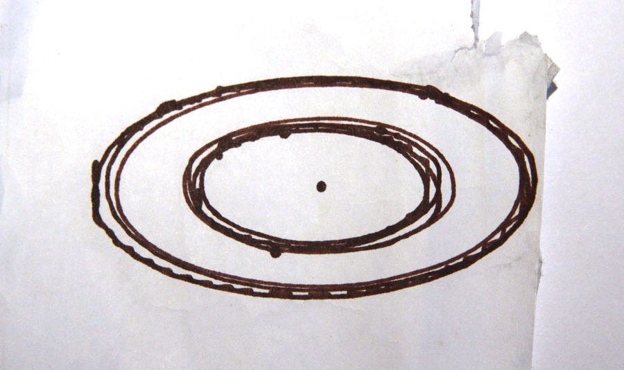
We performed the first tests using a doughnut-shaped 3D model sliced using ReplicatorG. ReplicatorG is the original software Makerbot used for its printers and works with early Makerbot products like the Thing-o-Matic. ReplicatorG allowed us to create a new slicing profile specifically for milling by selecting the appropriate "Profile Type".
Rather than using one of the copper boards for our first test, we attached a marker to the motor to ensure the Makerbot could receive and read the appropriate commands from the computer.
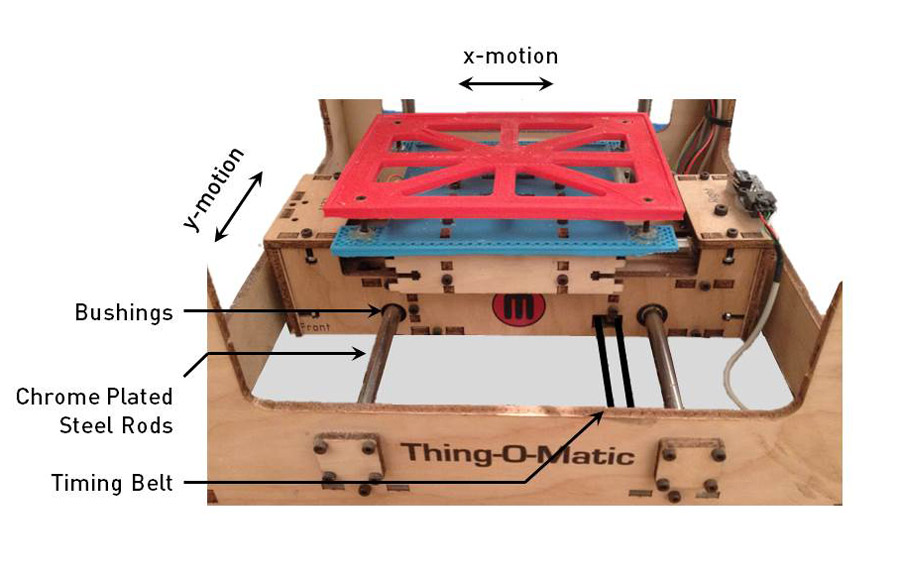
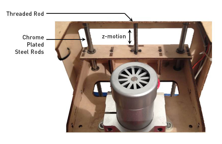
Straight out of the box, the Thing-o-Matic suits the needs of a PCB engraver because it is capable of precisely moving its head in a 3D space using its X, Y and Z carriages. However, some modifications were necessary in order to adapt it from a 3D printing tool to a PCB engraver.
Two major changes included:
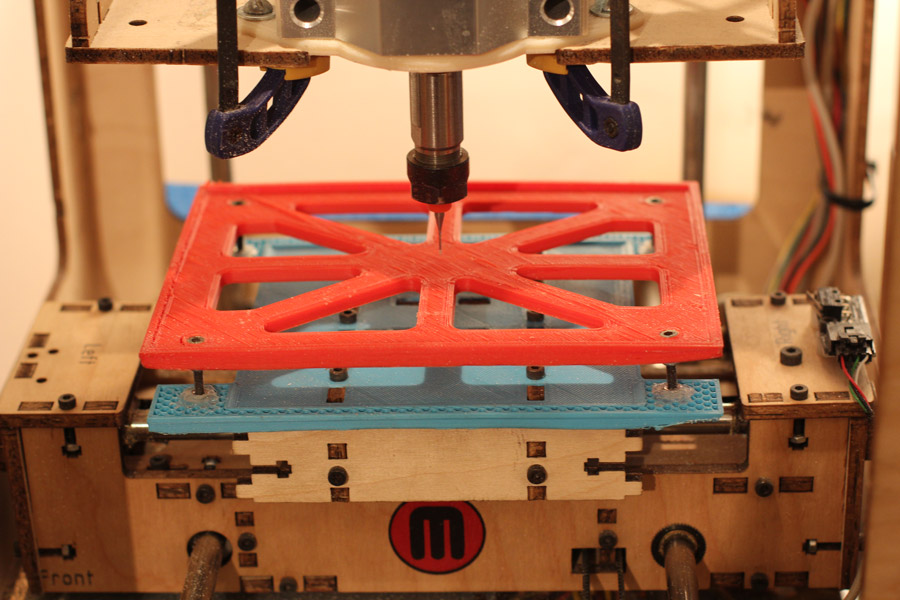
In order to ensure the PCB was steady while being engraved, we needed to create a 'stage' to hold the board. The PCB holder consists of two parts:
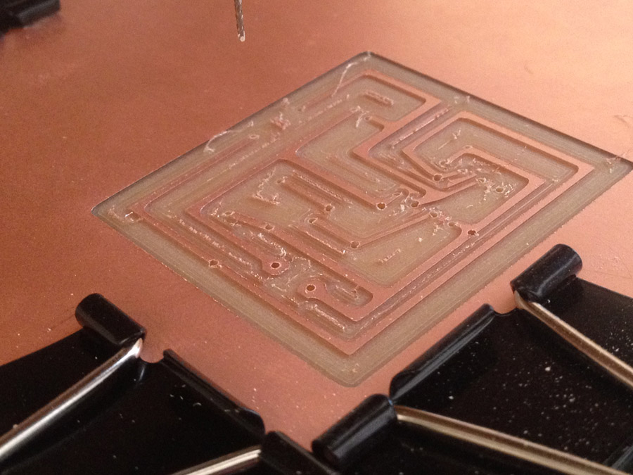
In addition, to ensure a secure board while engraving, we hold the circuit in place on the platform using binder clips.
The motor is mounted on a 3D printed mount that takes advantage of the holes already on the Z carriage to rigidly hold the motor. This prevents vibrations that could negatively affect a print.
We added a tap collet to connect the end mill bits to the motor, ensuring additional support in center of rotation of the motor. If the bit was eccentric, the routing would be unsuccessful and it would cause increased vibrations within the motor and frame.
Makerware, the software that is used to run the Makerbot, outputs its GCode files with the extension .X3G. This is a proprietary extension, making troubleshooting difficult, and is not compatible with other software we may use in the future. Furthermore, while Makerware is a useful tool for slicing STL files for 3D printing (an additive process), it is not able to create GCodes for PCB milling (a subtractive process). To create the most direct path to producing the circuits, we sought to eliminate Makerware from this process and allow interfacing from EagleCAD directly.
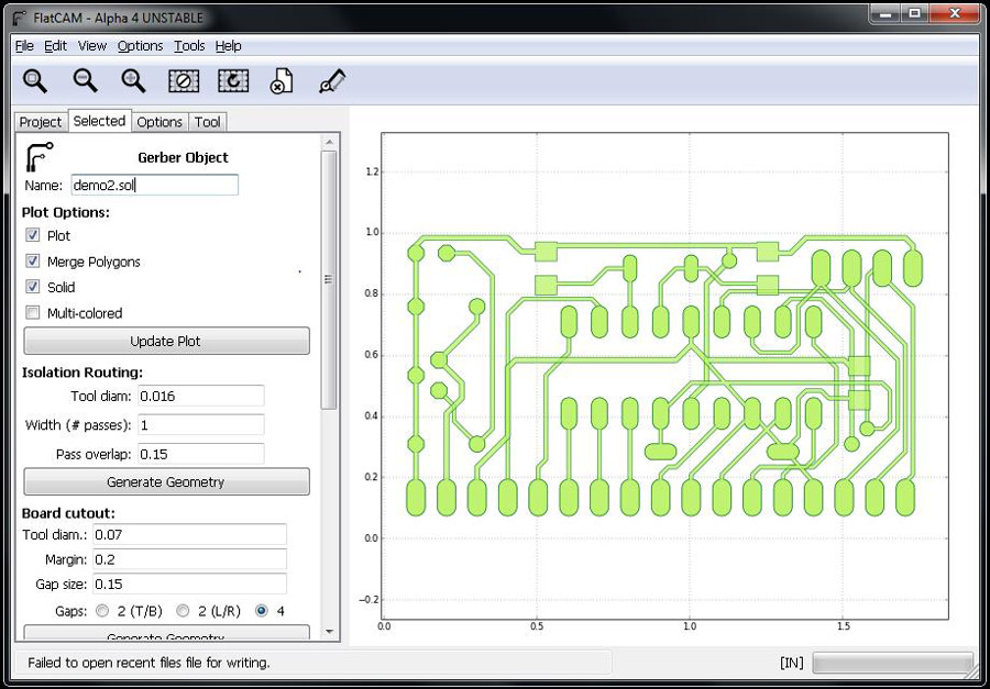
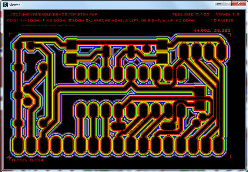
FlatCAM comes as an executable for Windows and has a user-friendly UI. It also accepts Gerber files. One of the capabilities of FlatCAM, not offered by other software packages, is the ability to have a live preview of the routing path as the settings are modified in the UI.
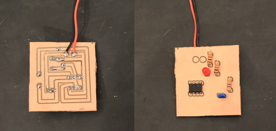
Using a 0.8mm diameter end mill, we chose a simple flashing LED circuit, with a 555 timer, to test as our first working circuit. We generated the tool paths using FlatCAM, and tested both the simple isolation as well as the cleanout option. Isolation refers to a single routing path around all traces, pads and vias, while cleanout will remove all unnecessary copper.
Once routed, the components were easily soldered onto the board. Since we used through-hole components, it was necessary to route both sides of the PCB, even though the board is only single-sided. Our first test produced a successful board!
In the future, the frame of the Makerbot Thing-o-Matic would need to be reinforced in order to increase the accuracy of the routing. We also intend to reprint the PCB holding platform (red) as a solid object, and with a higher infill percentage to increase its rigidity so that it will not flex when the end mill plunges into the PCB. If done sufficiently, the machine could potentially be used as a 3D CNC milling machine, not just a 2D router!
